B/128, GIDC Electronics Estate, Sector-25,Gandhinagar - 382025, Gujarat, India.

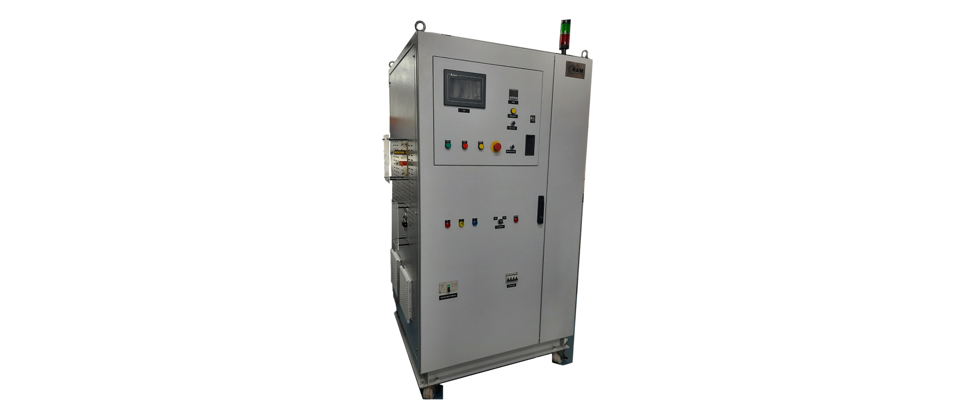
Specification: Model No: IPS2202221018
Sr. No. | Parameter | Specification | |
|---|---|---|---|
| A | Specifications of Pulsed DC power supply | ||
| 1 | Input Parameters | ||
| 1.1 | Input Voltage | 3-Phase, 415V ±10% AC, 50Hz | |
| 1.2 | Input connections | 5 wire (R,Y,B,N and Earth) | |
| 2 | Output Parameters | ||
| Voltage | |||
| 2.1 | Output voltage polarity | Pulsed DC negative output (pulsed between zero and negative peak). Important: The positive terminal of the power supply should be grounded. | |
| 2.2 | Peak output voltage | -1000 V max. [must be with a step size of 1V] | |
| 2.3 | Voltage ripple | 0.5% or better (at maximum rated values) | |
| 2.4 | Voltage regulation | 0.1% or better (at maximum rated values) | |
| 2.5 | Output current | 25A / 40A / 60A / Higher | |
| 2.6 | Max. Output Power | 25 /40 / 60 kW | |
| 2.7 | Pulse frequency | 20 kHz fixed | |
| 2.8 | Pulse duty cycle | Continuous duty operation | |
| 2.9 | Output Waveforms | Image at the end of this Specification | |
| 3 | Protections | ||
| 3.1 | Over current protection | Whenever over current [i.e. 150% of maximum rated value] or short circuit is detected then the power supply should respond as per following:
| |
| 3.2 | Short circuit protection | 10 consecutive overcurrent [OC] trips may be considered as short circuit and the power supply may be tripped | |
| 3.3 | Output over voltage | Power supply must trip if output voltage exceeds maximum rated voltage. Indication should be on the front panel. | |
| 4 | Output load | The final negative pulsed DC output will be connected to a resistive (plasma) load and positive terminal will be connected to ground. (The power supply must satisfactorily work in this configuration i. e. at plasma load) | |
| 5 | Front Panel Indications and Controls | ||
| 5.1 | Mains on/off | Suitable MCCB must be provided. | |
| 5.2 | Start/stop | Push button switches for power supply start/stop | |
| 5.3 | Emergency switch | To turn off the supply in the event of emergency | |
| 5.4 | Trip display | Indication Lamps (For all different trips) | |
| 5.5 | Trip reset | Push button switch for trip reset | |
| 5.6 | Output voltage control | Linearly variable from 100 to -1000V | |
| 5.7 | Output peak voltage display | Voltage should be displayed on digital panel meter with ± 1V accuracy | |
| 5.8 | Output peak current display | Peak pulsed current should be displayed on digital panel meter with ± 1A accuracy | |
| 5.9 | Output duty cycle control | Linearly variable from 10% to 80% via 10 turn potentiometer | |
| 5.10 | Output duty cycle display | Duty cycle should be displayed on digital panel meter with ± 1% accuracy | |
| 5.11 | Timer (digital) | Set time duration [in HH:MM] [Maximum 99.59] and Remaining time display | |
| 5.12 | Temperature measurement and display |
| |
| 6 | Duty of operation | Continuous duty (24 x 7 continuous operation) | |
| 7 | Interlocks | ||
| 7.1 | Timer | Time format should be hh:mm which can be fixed up to 99:59 hours as per process time duration. This timer should display set and remaining time in the same format. Initially both set time and remaining time should be same. Timer should start by pressing the start timer button. On completion of time duration applied voltage should be reduced to 0V. | |
| 7.2 | Chamber open interlock | An external interlock must be provided for preventing start of pulsed power supply, if the vacuum chamber is open.(A NO/NC change-over contact will be provided by us) | |
| 8 | Input/output Terminations | Input and Output – Screw terminal blocks with proper nomenclature | |
| 9 | Environmental conditions [Power supply should be capable to work in following environmental conditions] | ||
| 9.1 | Ambient Temperature | Up to 50ºC | |
| 9.2 | Humidity | Up to 95% RH | |